Table of Contents
Block Diagram and Schematic
ODROID-C1 targets to be a cheap, small and flexible enough computer for daily life.
Built with ARM Cortex-A5 Quad-core CPU and Mali450MP2 GPU, and open source software, ODROID-C1 can serve as a platform to make lots of applications for different purposes.
Schematics and drawings are available here.
For the new C1+
http://www.hardkernel.com/main/products/prdt_info.php?g_code=G143703355573&tab_idx=2
For the original C1
http://www.hardkernel.com/main/products/prdt_info.php?g_code=G141578608433&tab_idx=2
C1+ has below improvements from the original C1
- Change the HDMI connector to Type-A from Type-D.
- Improved SD card compatibility
- CEC function regardless of the RTC backup battery installation
- Power path from USB OTG port as well as DC-Jack
- Expose I2S signals for external audio DAC
ODROID-C1+

ODROID-C1
Specifications
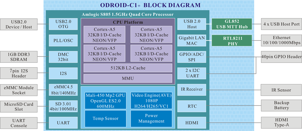
| Processor | Amlogic S805 : Quad Core Cortex™-A5 processor with Dual Core Mali-450 GPU |
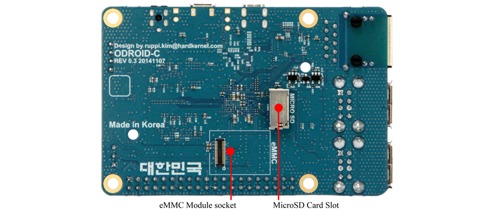
| eMMC module socket | 8GB/64GB : Toshiba eMMC 16GB/32GB : Sandisk iNAND Extreme The eMMC storage access time is 2-3 times faster than the SD card. You can purchase 4 size options: 8GB, 16GB, 32GB and 64GB. Using an eMMC module will increase speed and responsiveness, similar to the way in which upgrading to a Solid State Drive (SSD) in a typical PC also improves performance over a mechanical hard drive (HDD). |
| Micro Secure Digital (MicroSD) Card slot | There are two different methods of storage for the operating system. One is by using a MicroSD Card and another is using an eMMC module, which is normally used for external storage for smartphones and digital cameras. The ODROID-C1 can utilize the newer UHS-1 SD model, which is about 2 times faster than a normal class 10 card. Note that there are some cards which needs additional booting delay time around 30 seconds. According to our test, most Sandisk Micro-SD cards don't cause the booting delay. We will make a compatibility list soon. |
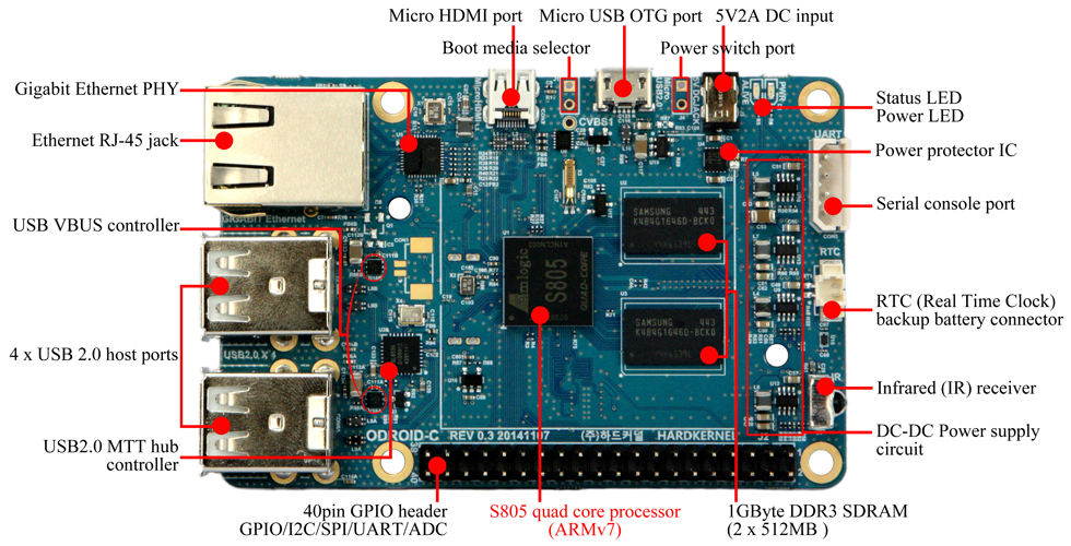
| 5V2A DC input | his is for 5V power input, with an inner diameter of 0.8mm, and an outer diameter of 2.5mm. The ODROID-C1 consumes less than 0.5A in most cases, but it can climb to 2A if many passive USB peripherals are attached directly to the main board. |
| USB host ports | There are four USB 2.0 host ports. You can plug a keyboard, mouse, WiFi adapter, storage or many other devices into these ports. You can also charge your smartphone with it! If you need more than 4 ports, you can use a powered external USB hub to reduce the power load on the main device. |
| Micro HDMI port | To minimize the size of the board, we used the Type-D micro-HDMI connector. |
| Ethernet RJ-45 jack | The standard RJ45 Ethernet port for LAN connection supports 10/100/1000Mbps speed. Green LED Flashes when there is 100Mbps connectivity Yellow(Orange) LED Flashes when there is 1000Mbps connectivity |
| Status / Power LEDs | The ODROID-C1 has four indicator LEDs that provide visual feedback. Red LED : Power Hooked up to 5V power Blue LED Alive Solid light : u-boot is running Flashing : Kernel is running (heart beat) |
| Infrared (IR) receiver | This is a remote control receiver module that can accept standard 37.9Khz carrier frequency based wireless data in NEC format. |
| Micro USB OTG port | You can use the standard micro-USB connector with Linux Gadget drivers on your host PC, which means that the resources in the ODROID-C1 can be shared with typical PCs. You can also add a micro-USB to HOST connector if you need an additional USB host port. Note that this port cannot be used for power input if you have the original C1. C1+ can accept the power input. |
| General Purpose Input and Output (GPIO) ports | These 40pin GPIO port can be used as GPIO/I2C/SPI/UART/ADC for electronics and robotics. The 40 GPIO pins on an ODROID-C1 are a great way to interface with physical devices like buttons and LEDs using a lightweight Linux controller. If you’re a C/C++ or Python developer, there’s a useful library called WiringPi that handles interfacing with the pins. We’ve already ported the WiringPi v2 library to ODROID-C1. Note that all the GPIO ports are 3.3Volt. The ADC inputs are limited to 1.8Volt. |
| Serial console port | Connecting to a PC gives access to the Linux console. You can see the log of the boot, or to log in to the C1 to change the video or network settings. Note that this serial UART uses a 3.3 volt interface. We recommend the USB-UART module kit from Hardkernel. Molex 5268-04a(2.5mm pitch) is mounted on the PCB. Its mate is Molex 50-37-5043 Wire-to-Board Crimp Housing. |
| RTC (Real Time Clock) backup battery connector | If you want to add a RTC functions for logging or keeping time when offline, just connect a Lithium coin backup battery (CR2032 or equivalent). All of the RTC circuits are included on the ODROID-C1 by default. Molex 53398-0271 1.25mm pitch Header, Surface Mount, Vertical type (Mate with Molex 51021-0200) |
| Gigabit Ethernet PHY | Realtek RTL8211F is a highly integrated Ethernet transceiver that complies with 10Base-T, 100Base-TX, and 1000Base-T IEEE 802.3 standards. |
| USB MTT hub controller | GENESYS LOGIC GL852G is used to implement the 4-port Hub function which fully complies with Universal Serial Bus Specification Revision 2.0. |
| USB VBUS controller | NCP380 Protection IC for USB power supply from OnSemi. |
| Boot media selector | If this port is opened, the first boot media is always eMMC. If this port is closed, the first boot media is always SD-card. |
| Power switch port | You can add a slide switch or rocker switch on this port if you want to implement a hardware on/off switch. If this port is closed, the power is off. If this port is opened, the power is on. |
| Power supply circuit | Discrete DC-DC converters LDOs are used for CPU/DRAM/IO power supply. |
| Power protector IC | NCP372 Over-voltage, Over-current, Reverse-voltage protection IC from OnSemi. |
Due to the limited power output from a computer's USB port, we suggest only powering the ODROID-C1 with a good quality 5V/2A PSU
Expansion Connectors
The Odroid-c1 povides one 40-pin dual row expansion header “J2”.
The location and pinout of these connectors is illustrated blew.
All signals on expansion headers are 3.3V except Analog input signal(1.8V).
Built-in pull-up/down resistor value is 60Kohm in the GPIOs.
J2 - 2×20 pins
| Pin Number | Expansion Net Name | Description | Driving Capability | Pin Number | Expansion Net Name | Description | Driving Capability |
|---|---|---|---|---|---|---|---|
| 1 | 3.3V Power | 2 | 5.0V Power | ||||
| 3 | I2CA_SDA | Export GPIO#74 | 4 | 5.0V Power | |||
| 5 | I2CA_SCL | Export GPIO#75 | 6 | Ground | |||
| 7 | GPIOY.BIT3 | Export GPIO#83, Wiring Pi GPIO#7 | 2mA | 8 | TXD1 | Export GPIO#113 | |
| 9 | Ground | 10 | RXD1 | Export GPIO#114 | |||
| 11 | GPIOY.BIT8 | Export GPIO#88, Wiring Pi GPIO#0 | 3mA | 12 | GPIOY.BIT7 | Export GPIO#87, Wiring Pi GPIO#1 | 2mA |
| 13 | GPIOX.BIT19 | Export GPIO#116, Wiring Pi GPIO#2 | 2mA | 14 | Ground | ||
| 15 | GPIOX.BIT18 | Export GPIO#115, Wiring PI GPIO#3 | 2mA | 16 | GPIOX.BIT7 | Export GPIO#104, Wiring Pi GPIO#4 | 3mA |
| 17 | 3.3V Power | 18 | GPIOX.BIT5 | Export GPIO#102, Wiring Pi GPIO#5 | 3mA | ||
| 19 | GPIOX.BIT10(MOSI) | Export GPIO#107, Wiring Pi GPIO#12, PWM1 | 2mA | 20 | Ground | ||
| 21 | GPIOX.BIT9(MISO) | Export GPIO#106, Wiring Pi GPIO#13 | 3mA | 22 | GPIOX.BIT6 | Export GPIO#103, Wiring Pi GPIO#6 | 3mA |
| 23 | GPIOX.BIT8(SPI_SCLK) | Export GPIO#105, Wiring Pi GPIO#14 | 4mA | 24 | GPIOX.BIT20 | Export GPIO#117, Wiring Pi GPIO#10 | 2mA |
| 25 | Ground | 26 | GPIOX.BIT21 | Export GPIO#118, Wiring Pi GPIO#11 | 2mA | ||
| 27 | I2CB_SDA | Export GPIO#76 | 28 | I2CB_SCL | Export GPIO#77 | ||
| 29 | GPIOX.BIT4 | Export GPIO#101, Wiring Pi GPIO#21 | 3mA | 30 | Ground | ||
| 31 | GPIOX.BIT3 | Export GPIO#100, Wiring Pi GPIO#22 | 3mA | 32 | GPIOX.BIT2 | Export GPIO#99, Wiring Pi#26 | 3mA |
| 33 | GPIOX.BIT11 | Export GPIO#108, Wiring Pi GPIO#23, PWM0 | 3mA | 34 | Ground | ||
| 35 | GPIOX.BIT0 | Export GPIO#97, Wiring Pi GPIO#24 | 3mA | 36 | GPIOX.BIT1 | Export GPIO#98, Wiring Pi GPIO#27 | 3mA |
| 37 | ADC.AIN1 | 10bit ADC#1 (0~1.8Volt) | 38 | 1.8V Power | For ADC reference voltage. Output! | ||
| 39 | Ground | 40 | ADC.AIN0 | 10bit ADC#0 (0~1.8Volt) |

J7 - 1×7 pins
This I2S expansion connector exists only on the C1+
| Pin Number | Expansion Net Name | Description | Driving Capability |
|---|---|---|---|
| 1 | Ground | ||
| 2 | GPIOAO.BIT6 | SPDIF Output | 2mA |
| 3 | P5V0 | 5.0V Power | |
| 4 | GPIOAO.BIT8 | I2S MCLK | 2mA |
| 5 | GPIOAO.BIT10 | I2S LRCLK | 2mA |
| 6 | GPIOAO.BIT9 | I2S SCLK | 2mA |
| 7 | GPIOAO.BIT11 | I2S Data Output | 2mA |

UART Console Connector
_____UART____
|Pin 4 - GND|
|Pin 3 - RXD|
|Pin 2 - TXD|
|Pin 1 - VCC|
\___________|

CON5
3.3V LVTTL
Enable the OTG device function on ODROID-C1+
C1+ PCB Rev 0.4 2015/09/30 has a new jumper J8.
Remove the Jumper on J8 if you don't use the USB OTG port as a power input
It will reduce the power consumption and heat significantly.

Remove the J8 jumper to make a stable access to the device mode (Gadget driver or ADB/Fastboot interface).

If you remove the J8 Jumper, the power path from the micro-USB port is disabled.
If your C1+ PCB is previous version, you need to desolder the R94 as described in this link.
http://forum.odroid.com/viewtopic.php?f=113&t=16864&p=110766&hilit=r94#p110766
Caution : Over-Voltage Protection feature
1. The power source must be connected to the DC-Jack.
Micro-USB-OTG and other 5Volt rails have not the protection feature.
2. Micro-USB power path Jumper(J8) must be removed to enable the Over-Voltage Protection.
3. Maximum over-voltage must be lower than 16Volt.
