This is an old revision of the document!
UART interface using the C1 Tinkering Kit
There are two UART ports on the C1.
The first one is mapped to /dev/ttyS2 which is connected to 40-pin header Pin #8 & #10.
The second one is mapped to /dev/ttyS0 which is connected to Serial Console Port CON5.
How to test external UART pin on the 40-pin header
You need to prepare below items.
- ODROID-C1
- USB-UART Module Kit
- jumper wire x4
- serial comunication utility on your Host PC
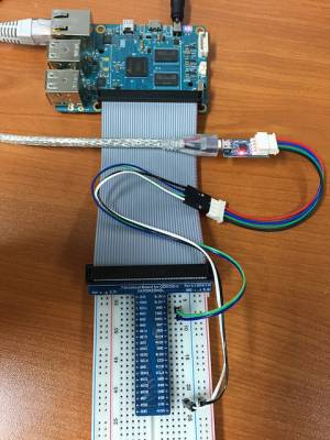
You will connect jumper wire as below picture.
Connect the USB-PORT of USB-UART Module to your HOST PC
The RXD and TXD must be twisted each other.
1. HOST PC setup.
You will open USB Module Device on your HOST PC.
Ubuntu
Install serial comunication utility.
sudo apt-get install minicom
After check your usb serial node, Open serial port.
ls /dev/ttyUSB*
sudo minicom -b 115200 -D /dev/ttyUSB0
2. Target board(ODROID-C1) setup.
Set a serial node on your ODROID-C1
stty -F /dev/ttyS2 115200
3. ODROID-C1 → HOST PC test.
ODROID-C1
echo 1 > /dev/ttyS2
4. HOST PC → ODROID-C1 test.
ODROID-C1
cat /dev/ttyS2
HOST PC
Send characters via minicom.
Pin Map : UART pin on the 4-pin CON5 connector
_____UART____
|           |
|Pin 4 - GND|
|Pin 3 - RXD|
|Pin 2 - TXD|
|Pin 1 - VCC|
|_          |
  |_________|
3.3V LVTTL

