This is an old revision of the document!
Table of Contents
Block Diagram and Schematic
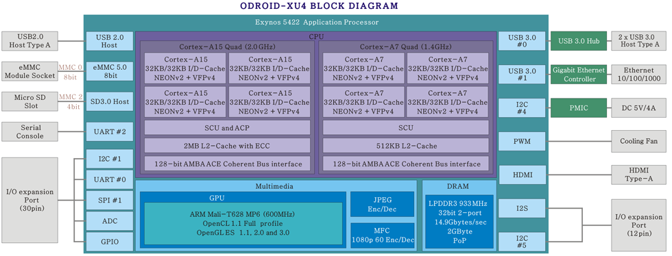
ODROID-XU4 is a new generation of computing device with more powerful, more energy-efficient hardware and a smaller form factor.
Offering open source support, the board can run various flavors of Linux, including the latest Ubuntu 15.04 and Android 4.4 KitKat and 5.0 Lollipop.
By implementing the eMMC 5.0, USB 3.0 and Gigabit Ethernet interfaces, the ODROID-XU4 boasts amazing data transfer speeds,
a feature that is increasingly required to support advanced processing power on ARM devices.
This allows users to truly experience an upgrade in computing, especially with faster booting, web browsing, networking, and 3D games.
The XU4 is fully software compatible with XU3!
However, the XU4 is more compact, more affordable and more expandable.
Schematics and drawings are available here.
http://www.hardkernel.com/main/products/prdt_info.php?g_code=G143452239825&tab_idx=2
Specifications
| Processor | Samsung Exynos5 Octa ARM Cortex™-A15 Quad 2Ghz and Cortex™-A7 Quad 1.3GHz CPUs |
| Memory | 2Gbyte LPDDR3 RAM at 933MHz (14.9GB/s memory bandwidth) PoP stacked |
| 3D Accelerator | Mali-T628 MP6(OpenGL ES 3.0/2.0/1.1 and OpenCL 1.1 Full profile) |
| Video | supports 1080p via HDMI cable(H.264+AAC based MP4 container format) |
| Video Out | Standard Type A HDMI connector |
| Audio | Instead of On-board Audio codec, There is I2S Expansion Port(CON11) |
| USB3.0 Host | SuperSpeed USB standard A type connector x 2 port, Max Load: 900mA/port |
| USB2.0 Host | High Speed standard A type connector x 1 ports, Max Load: 500mA/port |
| Display | HDMI monitor |
| Storage (Option) | MicroSD Card Slot, eMMC module socket : eMMC 5.0 HS4000 Flash Storage |
| Gigabit Ethernet LAN | 10/100/1000Mbps Ethernet with RJ-45 Jack ( Auto-MDIX support) |
| Serial console port | Connecting to a PC gives access to the Linux console. You can see the log of the boot, or to log in to the C1 to change the video or network settings. Note that this serial UART uses a 1.8 volt interface. We recommend the USB-UART module kit from Hardkernel. Molex 5268-04a(2.5mm pitch) is mounted on the PCB. Its mate is Molex 50-37-5043 Wire-to-Board Crimp Housing. |
| RTC (Real Time Clock) backup battery connector | If you want to add a RTC functions for logging or keeping time when offline, just connect a Lithium coin backup battery (CR2032 or equivalent). All of the RTC circuits are included on the ODROID-XU4 by default. Molex 53398-0271 1.25mm pitch Header, Surface Mount, Vertical type (Mate with Molex 51021-0200) |
| WiFi (Option) | USB IEEE 802.11b/g/n 1T1R WLAN with Antenna (USB module) |
| HDD/SSD SATA interface (Optional) | SuperSpeed USB (USB 3.0) to Serial ATA3 adapter for 2.5“/3.5” HDD and SSD storage |
| Power (included) | 5V 4A Power |
| Case(Option) | Mechanical case & cooler (98 x 74 x 29 mm approx. ) |
| PCB Size | 94 x 70 x 18 mm approx. |
Expansion Connectors
The XU3/XU4 povides one 30-pin dual row expansion header “CON10”.
The location and pinout of these connectors is illustrated blew. All signals on expansion headers are 1.8V except PWRON signal.
CON10 - 2×15 pins
| Pin Number | Net Name | GPIO & Export No | Default Pin State | Pin Number | Net Name | GPIO & Export No | Default Pin State |
|---|---|---|---|---|---|---|---|
| 1 | 5V0 | 2 | GND | ||||
| 3 | ADC_0.AIN0 | XADC0AIN_0 | I | 4 | UART_0.RTSN | GPA0.2 (#173) | I(PUDN) |
| 5 | UART_0.CTSN | GPA0.3 (#174) | I(PUDN) | 6 | UART_0.RXD | GPA0.0 (#171) | I(PUDN) |
| 7 | SPI_1.MOISI | GPA2.7 (#192) | I(PUDN) | 8 | UART_0.TXD | GPA0.1 (#172) | I(PUDN) |
| 9 | SPI_1.MISO | GPA2.6 (#191) | I(PUDN) | 10 | SPI_1.CLK | GPA2.4 (#189) | I(PUDN) |
| 11 | SPI_1.CSN | GPA2.5 (#190) | I(PUDN) | 12 | PWRON | I | |
| 13 | XE.INT13 | GPX1.5 (#21) | I(PUDN) | 14 | I2C_1.SCL | GPB3.3 (#210) | I(PUDN) |
| 15 | XE.INT10 | GPX1.2 (#18) | I(PUDN) | 16 | I2C_1.SDA | GPB3.2 (#209) | I(PUDN) |
| 17 | XE.INT14 | GPX1.6 (#22) | I(PUDN) | 18 | XE.INT11 | GPX1.3 (#19) | I(PUDN) |
| 19 | XE.INT22 | GPX2.6 (#30) | I(PUDN) | 20 | XE.INT20 | GPX2.4 (#28) | I(PUDN) |
| 21 | XE.INT21 | GPX2.5 (#29) | I(PUDN) | 22 | XE.INT23 | GPX2.7 (#31) | I(PUDN) |
| 23 | ADC_0.AIN3 | XADC0AIN_3 | I | 24 | XE.INT17 | GPX2.1 (#25) | I(PUDN) |
| 25 | XE.INT15 | GPX1.7 (Soft I2C SCL) (#23) | I(PUDN) | 26 | XE.INT16 | GPX2.0 (#24) | I(PUDN) |
| 27 | XE.INT25 | GPX3.1 (Soft I2C SDA) (#33) | I(PUDN) | 28 | GND | ||
| 29 | VDD_IO(1.8V) | 30 | GND |
CON11 - 2×6 pins
CON11 is available only in XU4 not XU3.
| Pin Number | Net Name | GPIO & Export No | Default Pin State | Pin Number | Net Name | GPIO & Export No | Default Pin State |
|---|---|---|---|---|---|---|---|
| 1 | 5V0 | 2 | GND | ||||
| 3 | VDD_IO(1.8V) | 4 | I2C_5.SDA | GPA2.2 (#187) | I(PUDN) | ||
| 5 | XE.INT26 | GPX3.2 (#34) | I(PUDN) | 6 | I2C_5.SCL | GPA2.3 (#188) | I(PUDN) |
| 7 | I2S_0.SCLK | GPZ.0 (#225) | I(PUDN) | 8 | GND | ||
| 9 | I2S_0.CDCLK | GPZ.1 (#226) | I(PUDN) | 10 | I2S_0.SDO | GPZ.4 (#229) | I(PUDN) |
| 11 | I2S_0.LRCK | GPZ.2 (#227) | I(PUDN) | 12 | I2S_0.SDI | GPZ.3 (#228) | I(PUDN) |
LED Indicators
The ODROID-XU4 has four indicator LEDs that provide visual feedback.
1. Red LED
- Power: Hooked up to 5V power
2. Blue LED
- Alive Solid light : u-boot is running
- Flashing : Kernel is running (heart beat)
UART Console Connector
_____UART____
|Pin 4 - GND|
|Pin 3 - RXD|
|Pin 2 - TXD|
|Pin 1 - VCC|
\___________|

1.8V LVTTL
HDMI Reverse current
When you “pull out” the DC plug (HDMI still connected), the red LED stays ON if the HDMI monitor/TV generates some amount of reverse current.
It may needs about 5 to 15 seconds to discharge the current.
Before full discharging, the DC-jack connection may not start the board automatically.
You need to remove the HDMI cable or wait enough time of full discharging.
Compliance Archives
MicroSD Socket Handling Precautions
1. If your MicroSD-card doesn't satisfy following conditions, change to a new card.
- The dimensions of the card must be standards.
- Make especially sure that the standard deviation due to wear.
- The wear of the pads will cause extremely negative side effect.
2. Excessive external force to the connector may be a case of causing damage.
Operation as shown in the figure below, please do not do.
- The slope of the sides of the card insertion extraction direction.
- Twisting vertical and horizontal directions of the card in the inserted state.

3. To make a minimal volume of the connector, the card detection parts are exposed partially. So any excessive plugging force can break it like red dotted ellipse part.

4. Micro SD/ TransFlash 카드용 커넥터 입니다. 이러한 카드 이외의 것은 삽입하지 마십시오. 또, 카드의 역삽입 및 기울기, 뒤틀림 삽입은 하지 마십시오. 카드역삽입 방지 기구를 가지고 있지만, 카드역방향 및 뒤틀림 방향등 비정상적으로 무리하게 삽입하면 카드 및 커넥터 파손의 원인이 되는 일이 있습니다.
5. 카드 삽입 상태에서 카드를 빼는 방향 이외의 방향으로 무리한 힘을 주지 마십시오.
카드 및 커넥터 파손의 원인이 되는 일이 있습니다.
6. 카드의 재질상, 카드 삽발거에 의하여 표면이 긁힘이나 자국이 발생합니다만 품질, 제품 성능상의 문제는 없습니다. 카드의 굴곡강도의 규격은 10N입니다.
카드에 과다한 하중을 가하면 카드파손의 원인이 되기 때문에,주의 바랍니다.
