UART interface using the IO-Port #1
This page introduces how you can UART Interface using the IO-Port #1
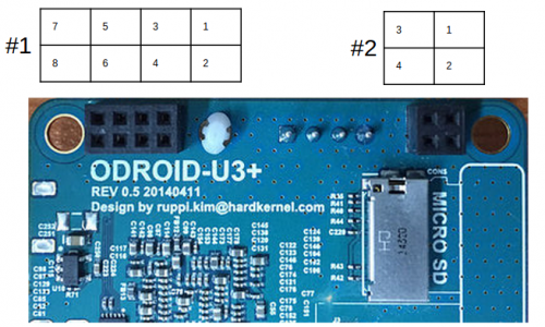
J4 - 2×4 pins(IO Port #1)
| Pin Number | Expansion Net Name | Export Number | Pin Number | Expansion Net Name | Export Number |
|---|---|---|---|---|---|
| 1 | XEINT_8 (GPX1.0) | #199 | 2 | 1.8V Power | |
| 3 | XEINT_9 (GPX1.1) | #200 | 4 | XURXD_0 (UART_0_RXD) | /dev/ttySAC0 |
| 5 | XEINT_13 (GPX1.5) | #204 | 6 | XUTXD_0 (UART_0_TXD) | /dev/ttySAC0 |
| 7 | Ground | 8 | 5V0 Power |
How to test your UART0 of IO-Port #1
You need to prepare below items.
- ODROID-U3
- USB-UART Module Kit
- jumper wire x4
- serial comunication utility on your Host PC
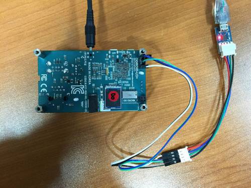
1. You will connect jumper wire to IO-Port #1.
This picture is that jumper is connected.
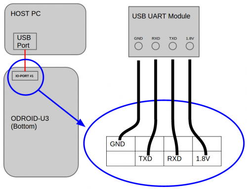
IO-PORT UART Block Diagram
2. HOST PC setup.
You will open USB Module Devices on your HOST PC.
Ubuntu
Install Serial comunication utility.
sudo apt-get install minicom
After check your usb serial node, Open serial port.
ls /dev/ttyUSB*
sudo minicom -b 115200 -D /dev/ttyUSB0
3. Target board(ODROID-U3) setup.
Set a serial node on your ODROID-U3
stty -F /dev/ttySAC0 115200
4. ODROID-U3 → HOST PC test.
ODROID-U3
echo 1 > /dev/ttySAC0
5. HOST PC → ODROID-U3 test.
ODROID-U3
cat /dev/ttySAC0
HOST PC
Send characters via minicom.


