This is an old revision of the document!
Table of Contents
Power On/Off switch
You can control power supplying to ODROID-C2 while DC adaptor is connected with external switch, Sliding or Toggle Switch for example, if you connect such switch to J4 on the board. J4 is connected to NCP372 (Protection IC). There is an ENABLE pin on the NCP372 and it is a low-active and have an internal pull-down resistor for default on.
| Switch status | Output of NCP372 | |
| ON(short) | OFF | |
| OFF(open) | ON (+5V) | |
With this hacking, we strongly recommend to shutdown the O/S completely before turn-off. Otherwise the file system could be corrupted very easily. In Linux, for example, please make sure to execute shutdown -r now or poweroff.
Alternative power input
The J8 pins are added for an alternative power input (for easier wiring/soldering to power supply cable on PCB rev0.2 20160226)

Alternative heartbeat LED
If you want to remap the blue heartbeat LED to other GPIO, refer this great instruction.
IR Remote Controller (Android)
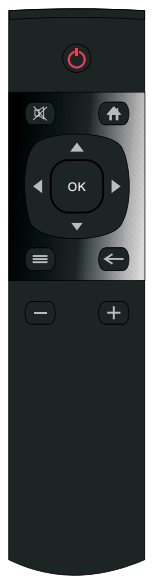 Manufacturer Code: 0x4DB2
| Button | IR code | Scancode | Android |
|---|---|---|---|
| Power | 0xDC | 116 | KEYCODE_POWER |
| Mute | 0x88 | 113 | KEYCODE_VOLUME_MUTE |
| Home | 0x82 | 102 | KEYCODE_HOME |
| OK | 0xCE | 97 | KEYCODE_DPAD_CENTER |
| Up | 0xCA | 103 | KEYCODE_DPAD_UP |
| Left | 0x99 | 105 | KEYCODE_DPAD_LEFT |
| Right | 0xC1 | 106 | KEYCODE_DPAD_RIGHT |
| Down | 0xD2 | 108 | KEYCODE_DPAD_DOWN |
| Menu | 0xC5 | 139 | KEYCODE_MENU |
| Back | 0x9A | 158 | KEYCODE_BACK |
| Volume Down | 0x81 | 109 | KEYCODE_VOLUME_DOWN |
| Volume Up | 0x80 | 104 | KEYCODE_VOLUME_UP |
The IR remote key map is defined in /system/etc/remote.conf file.
Default IR protocol is NEC type.
USB Hub IC reset
echo 126 > /sys/class/gpio/export
echo out > /sys/class/gpio/gpio126/direction
sleep 1
echo 0 > /sys/class/gpio/gpio126/value
sleep 1
echo 1 > /sys/class/gpio/gpio126/value
echo 126 > /sys/class/gpio/unexport
sleep 1
