Table of Contents
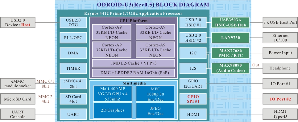
Block Diagram and Schematic
Although the ODROID-U3 is a cost-effective ARM single-board computer, it sports a quad-core Samsung ARM SoC.
The specifications on the ORDOID-U3 include a Samsung Exynos 4412 quad-core ARM Cortex-A9 1.7GHz SoC, Mali-400 MP with 4 GPU Cores, three USB 2.0 host ports, one 10/100MB Ethernet port, 1080p video output via micro-HDMI, 2GB of LP-DDR2 system memory, eMMC and micro-SD for storage, and supports Debian Wheezy, Ubuntu 14.04 Linux, Arch Linux, Kali Linux and Android Jellybean Operating Systems.
Schematics and drawings are available here. ODROID-U3 Schematics
| CPU | 1.7Ghz Exynos4412 Prime Cortex-A9 Quad-core processor |
| PMIC | MAX77686 Power Management IC from MAXIM |
| HSIC USB 2.0 Hub | USB3503A Integrated USB 2.0-compatible hub / HSIC upstream port from SMSC/Microchip |
| HSIC Ethernet controller | LAN9730 HSIC USB 2.0 to 10/100 Ethernet controller with HP Auto-MDIX from SMSC/Microchip |
| Audio CODEC | MAX98090 is a full-featured and high performance audio CODEC from MAXIM |
| Protection IC | NCP372 Over-voltage, Over-current, Reverse-voltage protection IC from OnSemi. |
| USB Load switch | NCP380 Protection IC for USB power supply from OnSemi. |
| HDMI conditioner | IP4791CZ12 HDMI transmitter interface protector with level shifter from NXP |
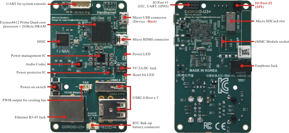
| Connectivity | USB Host x 3, Device x 1, Ethernet RJ-45, Headphone Jack |
| IO Ports | GPIO, UART, I2C, SPI(Board Revision 0.5 or higher) |
| Storage Slot | A Micro-SD slot and an eMMC module connector |
| DC Input | 5V / 2A input, Plug specification is inner diameter 0.8mm and outer diameter 2.5mm |
Expansion Connectors
The Odroid-U3 povides two expansion sockets which one 8-pin dual row expansion socket “J4” and other 4-pin dual row socket “J5”.
The location and pinout of these connectors is illustrated blew.
All signals on expansion headers are 1.8V level
J4 - 2×4 pins(IO Port #1)
| Pin Number | Net Name | GPIO & Export No | Pin Number | Net Name | GPIO & Export No |
|---|---|---|---|---|---|
| 1 | XEINT_8 | GPX1.0 (#199) | 2 | 1.8V | |
| 3 | XEINT_9 | GPX1.1 (#200) | 4 | XURXD_0 | /dev/ttySAC0 |
| 5 | XEINT_13 | GPX1.5 (#204) | 6 | XUTXD_0 | /dev/ttySAC0 |
| 7 | GND | 8 | 5V0 |
J5 - 2×2 pins(IO Port #2)
This socket is not provides at revision 0.3
| Pin Number | Net Name | GPIO & Export No | Pin Number | Net Name | GPIO & Export No |
|---|---|---|---|---|---|
| 1 | XSPICLK_1 | GPB.4 (#21) | 2 | XSPICSN_1 | GPB.5 (#22) |
| 3 | XSPIMOSI_1 | GPB.7 (#24) | 4 | XSPIMISO_1 | GPB.6 (#23) |
LED Indicators
RED LED(D3)- Power
- ON when it is Hooked up to 5V power.
- OFF when it is not Hooked up to 5V power.
BLUE LED(D2)- ALIVE
- dimly solid on when u-boot is running.
- blinking when Kernel is running(heart beat).
UART Console Connector
_____UART____
|Pin 4 - GND|
|Pin 3 - RXD|
|Pin 2 - TXD|
|Pin 1 - VCC|
\___________|

1.8V LVTTL

