Table of Contents
UART interface using the Tinkering Kit
There are two UART ports on the C2.
They are 3.3Volt (LVTTL) interface and there is no 5Volt tolerance.
The first one is mapped to /dev/ttyS1 which is connected to 40-pin header Pin #8 & #10 & ground pin.
The second one is mapped to /dev/ttyS0 which is connected to Serial Console Port CON5.
How to test external UART pin on the 40-pin header
You need to prepare below items.
- ODROID-C2
- USB-UART Module Kit
- jumper wire x4
- serial comunication utility on your Host PC
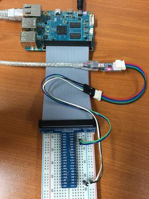
You will connect jumper wire as below picture.
Connect the USB-PORT of USB-UART Module to your HOST PC
The RXD and TXD must be twisted each other.
1. HOST PC setup.
You will open USB Module Device on your HOST PC.
Ubuntu
Install serial comunication utility.
sudo apt-get install minicom
After check your usb serial node, Open serial port.
ls /dev/ttyUSB*
sudo minicom -b 115200 -D /dev/ttyUSB0
2. Target board(ODROID-C2) setup.
Set a serial node on your ODROID-C2
stty -F /dev/ttyS1 115200
3. ODROID-C2 → HOST PC test.
ODROID-C2
echo 1 > /dev/ttyS1
4. HOST PC → ODROID-C2 test.
ODROID-C2
cat /dev/ttyS1
HOST PC
Send characters via minicom.
Pin Map : UART pin on the 4-pin CON5 connector
_____UART____
|           |
|Pin 4 - GND|
|Pin 3 - RXD|
|Pin 2 - TXD|
|Pin 1 - VCC|
|_          |
  |_________|
3.3V LVTTL
Another UART port on 40pin header
If you don't use an I2C interface(i2c-1) on pin#3 & pin#5, you can use them to activate the UART2.
Just follow campbell's development note to have a new UART2 port via /dev/ttyS2.
Note that Pin#3(SDA1) is mapped to Tx and Pin#5(SCL1) is Rx.
How to enable a third UART ttyS2 by "campbell"
Automatically configure the UART settings.
This is an example of default setting for a GPS module which has a 9600bpsN81 UART interface.
Add the following to the end of /etc/rc.local (before the exit 0)
/bin/stty -F /dev/ttyS2 raw 9600 cs8 clocal -cstopb > /dev/null 2>&1
This way the tty port is setup for use with the gps on system boot, without user interaction.
Tips for UART port
How to enable UART_B and UART_C ports
Up to 4 ports can be used for UART in ODROID-C2—UART_A0(Serial console), UART_A, UART_B and UART_C.
There are UART_A, UART_B and UART_C in expansion connectors of ODROID-C2.
- <UART pin> | <Pin number>
- UART_A TX | 8
- UART_A RX | 10
- UART_B TX | 3
- UART_B RX | 5
- UART_C TX | 32
- UART_C RX | 26
In order to enable UART_B and UART_C ports, it is necessary to modify the meson64_odroidc2.dts file.
1. Kernel source download
sudo apt-get update
sudo apt-get install git
git clone --depth 1 https://github.com/hardkernel/linux.git -b odroidc2-3.14.y
2. Delete I2C_A definition
I2C_A uses same pins as UART_B by pinmux. So, i2c_a definition needs to be removed.
- ($LINUX)/arch/arm64/boot/dts/meson64_odroidc2.dts
iff --git a/arch/arm64/boot/dts/meson64_odroidc2.dts b/arch/arm64/boot/dts/meson64_odroidc2.dts
index e6a25b0..db09b04 100755
--- a/arch/arm64/boot/dts/meson64_odroidc2.dts
+++ b/arch/arm64/boot/dts/meson64_odroidc2.dts
@@ -813,18 +813,6 @@

 };

-&i2c_a {
-       status = "okay";
-
-       /* Hardkernel I2C RTC */
-       pcf8563: pcf8563@51     {
-               status = "disabled";
-               compatible = "nxp,pcf8563";
-               reg = <0x51>;
-               #clock-cells = <0>;
-       };
-};
-
 &i2c_b {
        status = "okay";
3. Add UART_B and UART_C definitions
- ($LINUX)/arch/arm64/boot/dts/meson64_odroidc2.dts
diff --git a/arch/arm64/boot/dts/meson64_odroidc2.dts b/arch/arm64/boot/dts/meson64_odroidc2.dts
index e6a25b0..fd41552 100755
--- a/arch/arm64/boot/dts/meson64_odroidc2.dts
+++ b/arch/arm64/boot/dts/meson64_odroidc2.dts
@@ -31,6 +31,8 @@
        aliases {
                serial0 = &uart_AO;
                serial1 = &uart_A;
+               serial2 = &uart_B;
+               serial3 = &uart_C;
        };

        gpu_dvfs_tbl: gpu_dvfs_tbl {
@@ -459,6 +461,32 @@
                pinctrl-0 = <&a_uart_pins>;
        };

+       uart_B: serial@c11084dc {
+               compatible = "amlogic, meson-uart";
+               reg = <0x0 0xc11084dc 0x0 0x18>;
+               interrupts = <0 75 1>;
+               status = "okay";
+               clocks = <&clock CLK_XTAL>;
+               clock-names = "clk_uart";
+               fifosize = < 64 >;
+               pinctrl-names = "default";
+               pinctrl-0 = <&b_uart_pins>;
+               resets = <&clock GCLK_IDX_UART1>;
+       };
+
+       uart_C: serial@c1108700 {
+               compatible = "amlogic, meson-uart";
+               reg = <0x0 0xc1108700 0x0 0x14>;
+               interrupts = <0 93 1>;
+               status = "okay";
+               clocks = <&clock CLK_XTAL>;
+               clock-names = "clk_uart";
+               fifosize = < 64 >;
+               pinctrl-names = "default";
+               pinctrl-0 = <&c_uart_pins>;
+               resets = <&clock GCLK_IDX_UART2>;
+       };
+
        canvas {
                compatible = "amlogic, meson, canvas";
                dev_name = "amlogic-canvas";
4. Install modified dtb file
make odroidc2_defconfig
make dtbs
sudo cp -f arch/arm64/boot/dts/meson64_odroidc2.dtb /media/boot/
sudo reboot
5. Done
