Table of Contents
UART interface using the C1 Tinkering Kit
There are two UART ports on the C1/C0.
The first one is mapped to /dev/ttyS2 which is connected to 40-pin header Pin #8 & #10.
The second one is mapped to /dev/ttyS0 which is connected to Serial Console Port CON5.
How to test external UART pin on the 40-pin header
You need to prepare below items.
- ODROID-C1
- USB-UART Module Kit
- jumper wire x4
- serial comunication utility on your Host PC
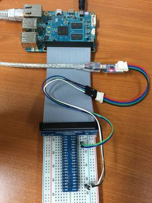
You will connect jumper wire as below picture.
Connect the USB-PORT of USB-UART Module to your HOST PC
The RXD and TXD must be twisted each other.
1. HOST PC setup.
You will open USB Module Device on your HOST PC.
Ubuntu
Install serial comunication utility.
sudo apt-get install minicom
After check your usb serial node, Open serial port.
ls /dev/ttyUSB*
sudo minicom -b 115200 -D /dev/ttyUSB0
2. Target board(ODROID-C1) setup.
Set a serial node on your ODROID-C1
stty -F /dev/ttyS2 115200
3. ODROID-C1 → HOST PC test.
ODROID-C1
echo 1 > /dev/ttyS2
4. HOST PC → ODROID-C1 test.
ODROID-C1
cat /dev/ttyS2
HOST PC
Send characters via minicom.
How to enable another UART /dev/ttyS1 on 40 Pin Header
Pin Map : GPIOX.4[29, TXD], GPIOX.5[18, RXD]
To use the UART(/dev/ttyS1), you first need to update the kernel version to “3.10.104” or higher.
sudo apt-get update && sudo apt-get upgrade && sudo apt-get dist-upgrade
1. Install the device-tree compiler package
sudo apt-get install device-tree-compiler
2. Download dts file from our github.
wget https://github.com/hardkernel/linux/raw/odroidc-3.10.y/arch/arm/boot/dts/meson8b_odroidc.dts
3. Edit dts file.
vi meson8b_odroidc.dts
4. find uart_ao & add uart_0 definition.
...
        uart_ao{
                compatible = "amlogic,aml_uart";
                port_name = "uart_ao";
                status = "okay";
                dev_name = "uart_ao";
                pinctrl-names = "default";
                pinctrl-0 = <&ao_uart_pins>;
        };

        /* edit & add code */
        uart_0{
                compatible = "amlogic,aml_uart";
                port_name = "uart_a";
                status = "okay";
                dev_name = "uart_0";
                pinctrl-names = "default";
                pinctrl-0 = <&a_uart_pins>;
        };
        /* end add */

        uart_1{
                compatible = "amlogic,aml_uart";
                port_name = "uart_b";
                status = "okay";
                dev_name = "uart_1";
                pinctrl-names = "default";
                pinctrl-0 = <&b_uart_pins>;
        };
...
5. find pinmux & add uart_0 pin mux.
...
        ao_uart_pins:ao_uart{
                amlogic,setmask=<10 0x1800>;
                amlogic,pins="GPIOAO_0", "GPIOAO_1";
                amlogic,pullup=<1>;
                amlogic,pullupen=<1>;
        };

        /* edit & add code */
        a_uart_pins:a_uart{
                amlogic,setmask=<4 0x30000>;
                amlogic,pins="GPIOX_4", "GPIOX_5";
                amlogic,pullup=<1>;
                amlogic,pullupen=<1>;
        };
        /* end add */

        b_uart_pins:b_uart{
                amlogic,setmask=<4 0x0300>;
                amlogic,pins="GPIOX_16", "GPIOX_17";
                amlogic,pullup=<1>;
                amlogic,pullupen=<1>;
        };
...
6. save dts file & compile dts file
dtc -O dtb -o ./meson8b_odroidc.dtb ./meson8b_odroidc.dts
7. update dtb file & reboot
sudo cp ./meson8b_odroidc.dtb /media/boot/meson8b_odroidc.dtb && sync
sudo reboot
Pin Map : UART pin on the 4-pin CON5 connector
_____UART____
|           |
|Pin 4 - GND|
|Pin 3 - RXD|
|Pin 2 - TXD|
|Pin 1 - VCC|
|_          |
  |_________|
3.3V LVTTL
Automatically configure the UART settings.
This is an example of default setting for a GPS module which has a 9600bpsN81 UART interface.
Add the following to the end of /etc/rc.local (before the exit 0)
/bin/stty -F /dev/ttyS2 raw 9600 cs8 clocal -cstopb > /dev/null 2>&1
This way the tty port is setup for use with the gps on system boot, without user interaction.
