This is an old revision of the document!
Table of Contents
Xprotolab Plain
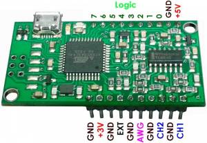
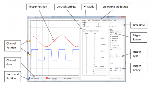
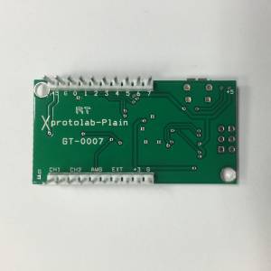
The Xprotolab Plain is a multi scope board created by Gabotronics. It is the most inexpensive but feature rich oscilloscope in the market. It consists of a simple DIP module with a USB interface. Visualization of the signals and controlling the oscilloscope is done on the PC interface software (open source). The Xprotolab Plain is similar to the original Xprotolab, but doesn't have the display and buttons, so it only works with the USB interface. The board measures only 1 x 2 inches, and can be mounted directly on a breadboard. The Xprotolab can also be used as a development board for the AVR XMEGA microcontroller.
Package include
- Xprotolab Plain (Connectors were soldered)
- 10 x IC hook
- Micro USB Cable
Documents & links
How to use
Xscopes Qt program
Build & Run
1. Install Qt packages
sudo apt-get update
XU4
sudo apt-get update
sudo apt-get install qt5-default libqt5serialport5-dev libusb-1.0-0-dev
sudo apt-get --reinstall install libgles2-mesa
C2
You must remove mali-fbdev package before installing qt5.
apt-get remove mali-fbdev
sudo apt-get install qt5-default libqt5serialport5-dev libusb-1.0-0-dev
apt-get download mali-fbdev
dpkg -i --force-overwrite mali-fbdev*.deb
C1
sudo apt-get update
sudo apt-get install qt5-default libqt5serialport5-dev libusb-1.0-0-dev
You should add swap space due to its limited RAM.
sudo fallocate -l 2G /swapfile
sudo mkswap /swapfile
sudo swapon /swapfile
After build, if you want to free
sudo swapoff -a
2. Get soure code
git clone https://github.com/ganzziani/xscopes-qt
3. Build
cd xscopes-qt
qmake
make -j8
4. Run
sudo ./xscope
5. Connect Xprotolab to your Board using micro USB cable.
6. Then, click “Connect” button in the “Options” tab on UI.
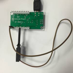
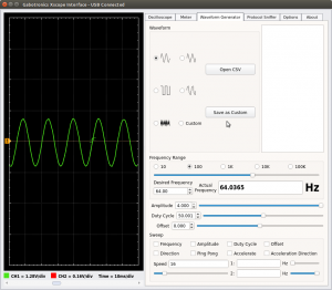
Oscilloscope echo test using AWG
H/W specifications
Pins description
| Name | Description | Comment |
|---|---|---|
| +5V | +5V Input voltage | Do not apply +5V if using the USB port |
| +3V | +3.3V Output voltage | 200mA max output |
| GND | Ground | It is recommended use all ground pins to reduce voltage offset errors. |
| CH1 | Analog Channel 1 | Input range : -14V to +20 V |
| CH2 | Analog Channel 2 | Input range : -14V to +20 V |
| AWG | Arbitrary Waveform Generator | Output range : +/- 2V |
| EXT | External Trigger | Digital input, max 5.5V |
| Logic 0 | Digital Channel 0 | I2C Sniffer signal : SDA |
| Logic 1 | Digital Channel 1 | I2C Sniffer signal : SCL |
| Logic 2 | Digital Channel 2 | UART Sniffer signal : RX |
| Logic 3 | Digital Channel 3 | UART Sniffer signal : TX |
| Logic 4 | Digital Channel 4 | SPI Sniffer signal : /SS |
| Logic 5 | Digital Channel 5 | SPI Sniffer signal : MOSI |
| Logic 6 | Digital Channel 6 | SPI Sniffer signal : MISO |
| Logic 7 | Digital Channel 7 | SPI Sniffer signal : SCK |
General specifications
- ATXMEGA32A4U 36KB Flash, 4KB SRAM, 1KB EEPROM
- Module size : 1.980“ x 1.01”
- PDI interface
- USB connectivity : Windows, Linux, MAC, Android
Oscilloscope specifications
- 2 Analog inputs
- Maximum sampling rate : 2MSPS
- Analog bandwidth : 200kHz
- Resolution : 8bits
- Input impedance : 1MΩ
- Buffer size per channel : 256
- Input voltage range : -14V to +20V
Logic Analyzer specifications
- 8 Digital Inputs, 3.3V level
- Maximum sampling rate : 2MSPS
- Frequency counter : 16Mhz
- Protocol sniffer : UART, I2C, SPI
- Internal pull up or pull down
- Buffer size : 256
AWG specifications
- 1 Analog output
- Maximum conversion rate : 1MSPS
- Analog Bandwidth : 44.1kHz
- Resolution : 8bits
- Output current : +/- 7mA
- Buffer size : 256
- Ouput voltage : +/- 2V
