Table of Contents
Introduction
You're probably itching to make some fun embedded computer projects with ODROID-XU4. What you need is an add on prototyping T-breakout board, which can break out all those tasty power, GPIO, I2C, ADC pins from the 40 pin header onto a solderless breadboard. This set will make “cobbling together” prototypes with the ODROID-XU4 super easy.
This kit comes with below many items.
- Assembled T-breakout PCB - 40Pin GPIO Breakout board
- Breadboard - 630 Tie-points with dual power lanes
- 40pin Ribbon cable - IDC Flat cable 100mm
- 40pin Male-to-Male Dupont jumper Wire 170mm
- 7 x Green LED 3mm
- 7 x Yellow LED 3mm
- 7 x Red LED 3mm
- 2 x Photo Cell (CdS Light sensor)
- 6 x Tact Switchs
- 50 x 330 Ohm 1/6W resister
- 50 x 10K Ohm 1/6W resister
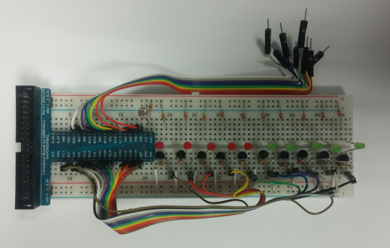
DIY light level meter project
Linux
1. Configuration tinkering kit such as below schematic.
Light Level Meter schematic
2. Get the wiringPi library compatible ODROID
# git clone https://github.com/hardkernel/wiringPi
3. Build the library
# cd wiringPi
# ./build
4. Compile and run the example source code.
- example-led.c
//------------------------------------------------------------------------------------------------------------
//
// ODROID-C GPIO(LED) / ADC Test Application.
//
// Defined port number is wiringPi port number.
//
// Compile : gcc -o <create excute file name> <source file name> -lwiringPi -lwiringPiDev -lpthread
// Run : sudo ./<created excute file name>
//
//------------------------------------------------------------------------------------------------------------
#include <stdio.h>
#include <stdlib.h>
#include <stdint.h>

#include <unistd.h>
#include <string.h>
#include <time.h>

#include <wiringPi.h>
#include <wiringPiI2C.h>
#include <wiringSerial.h>
#include <lcd.h>

//------------------------------------------------------------------------------------------------------------
//
// Global handle Define
//
//------------------------------------------------------------------------------------------------------------

#define DATA_UPDATE_PERIOD  100 // 100ms

//------------------------------------------------------------------------------------------------------------
//
// ADC:
//
//------------------------------------------------------------------------------------------------------------
#define PORT_ADC   0   // ADC.AIN0
#define MAX_ADC_VALUE	4095

//------------------------------------------------------------------------------------------------------------
//
// LED:
//
//------------------------------------------------------------------------------------------------------------
const int ledPorts[] = {
	7,
	0,
	2,
	3,
	12,
	13,
	14,
	21,
	22,
	23,
};

#define MAX_LED_CNT (sizeof(ledPorts) / sizeof(ledPorts[0]))
#define ADC_UNIT	(MAX_ADC_VALUE / MAX_LED_CNT)

//------------------------------------------------------------------------------------------------------------
//------------------------------------------------------------------------------------------------------------
//
// system init
//
//------------------------------------------------------------------------------------------------------------
int system_init(void)
{
    int i;

    // GPIO Init(LED Port ALL Output)
    for(i = 0; i < MAX_LED_CNT; i++)    pinMode (ledPorts[i], OUTPUT);

    return  0;
 }

//------------------------------------------------------------------------------------------------------------
//
// board data update
//
//------------------------------------------------------------------------------------------------------------
void boardDataUpdate(void)
{
    int i, adcValue, ledPos;

    // adc value read
    if((adcValue = analogRead (PORT_ADC)))    {
	ledPos = adcValue / ADC_UNIT;
    }
    else
        ledPos = 0;

    //  LED Control
    for(i = 0; i < MAX_LED_CNT; i++)    digitalWrite (ledPorts[i], 0); // LED All Clear
    for(i = 0; i < ledPos;      i++)    digitalWrite (ledPorts[i], 1); // LED On
}

//------------------------------------------------------------------------------------------------------------
//
// Start Program
//
//------------------------------------------------------------------------------------------------------------
int main (int argc, char *argv[])
{
    static int timer = 0 ;

    wiringPiSetup ();

    if (system_init() < 0)
    {
        fprintf (stderr, "%s: System Init failed\n", __func__);     return -1;
    }

    for(;;)    {
        usleep(100000);
        if (millis () < timer)  continue ;

        timer = millis () + DATA_UPDATE_PERIOD;

        // All Data update
        boardDataUpdate();
    }

    return 0 ;
}
Python example
0. Requrements install
# sudo apt update
# sudo apt install python-dev python-setuptools swig3.0
1. Get/setup WiringPi 2 for Python repository
# git clone https://github.com/hardkernel/WiringPi2-Python.git
# cd WiringPi2-Python
# git submodule init
# git submodule update
2. Build & install
# ./build.sh
Or
# swig3.0 -python -threads wiringpi.i
# sudo python setup.py build install
3. Run the example source code
- example-led.py
#!/usr/bin/python
import wiringpi2 as wpi
import time

leds = [7, 0, 2, 3, 12, 13, 14, 21, 22, 23]
wpi.wiringPiSetup()

# GPOI pin setup
for x in leds:
	wpi.pinMode(x, 1)
	wpi.digitalWrite(x, 0)

adc_unit = 4095 / len(leds)
while True:
	time.sleep(0.05)
	adcValue = wpi.analogRead(0)
	ledPos = adcValue / adc_unit
	for x in leds:
		wpi.digitalWrite(x, 0)

	for x in xrange(ledPos):
		wpi.digitalWrite(leds[x], 1)

